If you’re going to be venturing into building guitar pedals – one of the most valuable things you can build is a test box. Not only will it help you with your soldering skills, but it makes testing and debugging your builds far easier and quicker.
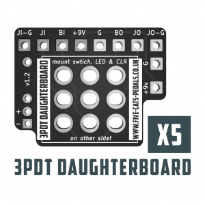
The build layout below uses one of our own 3PDT Daughterboards to make things a little easier (you can build one without, but you’ll need to wire the 3PDT manually). It also includes an Audio Probe – whilst this may not seem like something you’ll use as a beginner – as your builds progress and you inevitably hit some issues – it’s a super handy tool to have, and you’ll have one ready!
Why have an audio probe?
Sometimes you’ll build a board and have…no output. It sucks. Its frustrating…we’ve all been there…and it still happens. However – having an audio probe helps to find where in your circuit the audio signal is stopping.
It works by connecting the audio probe to the output jack tip whilst disconnecting the output from the board. So you place your audio probe at different points on the board and you’ll hear your signal through the output – follow the path until it stops….that’s where your issue is!
Will you need to follow the schematic for using an audio probe? Yes
Is it worth the time and effort to learn to read schematics to be able to audio probe you board? Yes
List of components
- Enclosure ( Hammond 1590B or bigger)
- 5 Speaker terminal connectors (we used these ones from Amazon that came in a pack of 8)
- 1 x 3PDT Footswitch
- 1 x 2PDT Toggle (on/on)
- 2 x 3mm LED (we picked one blue, one red)
- 2 x LED Lenses (optional)
- 2 x Mono Jacks
- 1 x 2.1mm DC Jack
- Multi-meter lead / length of wire / something to use as a probe (this is for the audio probe)
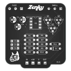
The layout
Here’s the layout for building your test box – there’s a lot of wiring going on here which can look daunting – but take things one step at a time. Here’s our build order (this is just a suggestion – build it how you want!)
Build plan
- Wire up the daughterboard to the speaker terminals
- Add the led and resistor to the daughterboard
- Wire up input/output to daughterboard
- Add the connections to the 2PDT
- Connect the DC Jack
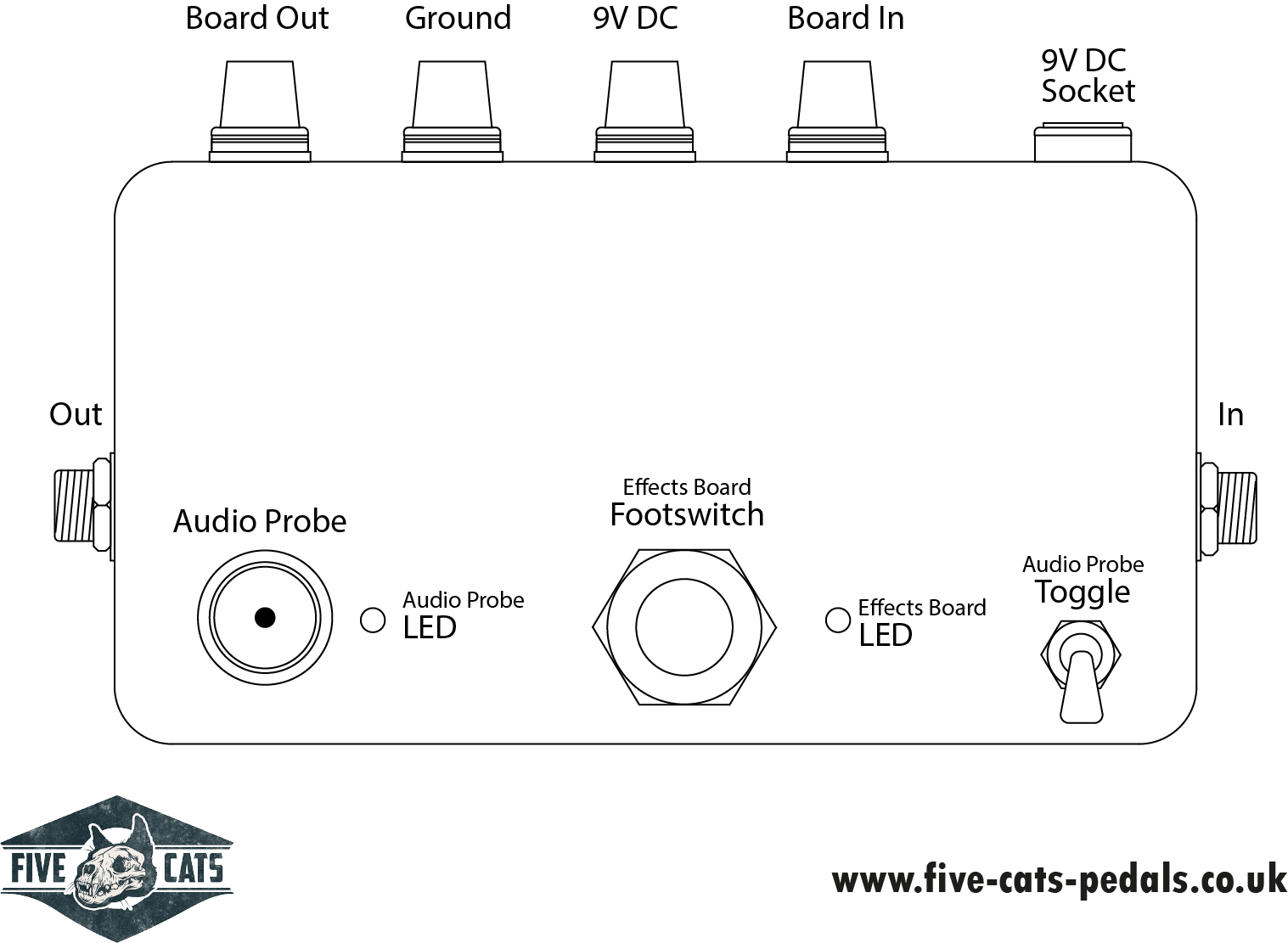
What goes where?

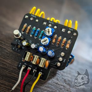
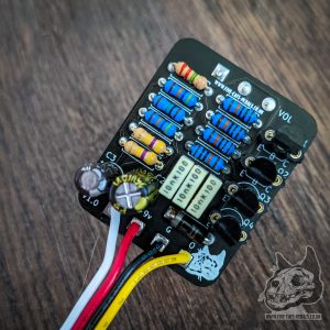
You can layout the box however you want – here’s how we did ours, but this isn’t gospel – make it your own! (the same as the finish on the enclosure, we lightly sanded ours and gave it some pattern finish with a round sanding disk – we’ll be doing a tutorial on that shortly!)
Testing….the test box
Once everything’s in the box – its time to fire it up…Firstly, check the bypass is working. Next up…connect a board to the speaker terminals (be sure to connect them to the right ones!) – press the footswitch – if all is well you’ll now have the board engaged!
The final test is the audio probe – you can’t test this until the above is working…so don’t skip the steps! Connect your audio probe to the audio probe connect (the 5th speaker terminal in our case), flip the toggle switch and you should see the LED light up, and the sound stop.
Now, place the end of your audio probe to the output pad on the board – you should now have the sound from your board again – if this happens – all is good, the audio probe is now working.
Put the back on the enclosure…go have a nice cup of coffee and admire your work!